


Wood Box Joints Explained: Layout, Fit and Common Cutting Mistakes
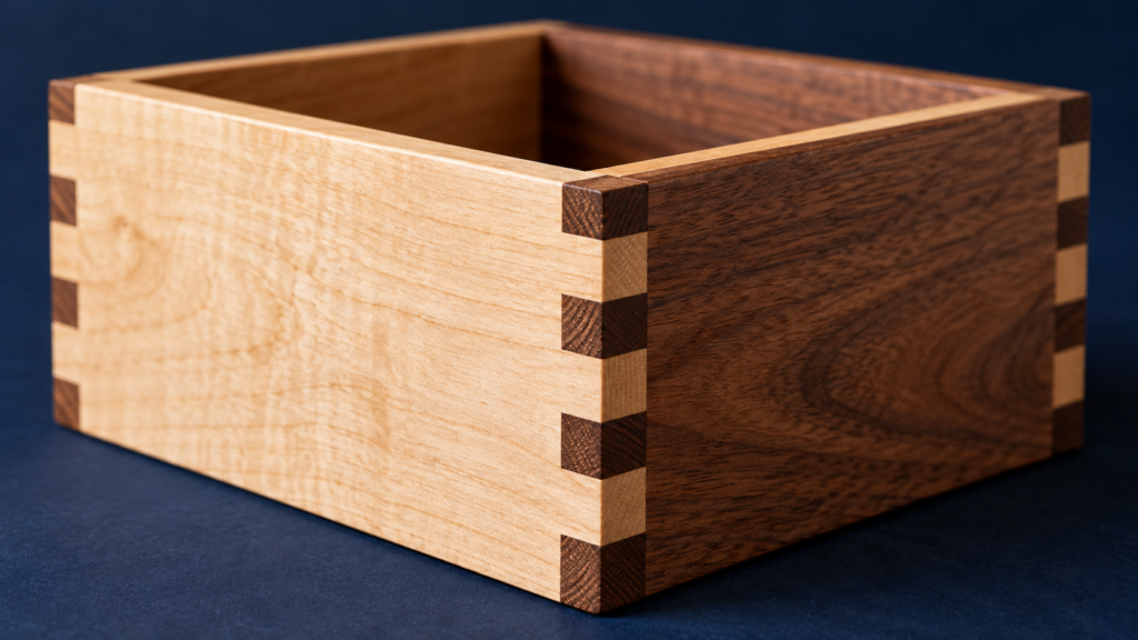
Wood box joints connect board ends with alternating rectangular fingers and matching spaces. They are common at box and drawer corners, where the visible end-grain pattern becomes part of the design. A useful fit review separates finger tightness, mating-board layout and how far the fingers project.
Those are different checks. A pair can have a sensible finger width but the wrong starting pattern. Another pair can mate properly while its fingers stand slightly proud of the adjoining surface. Treating every mismatch as “the bit is wrong” can send the next adjustment in the wrong direction.
Wood box joints use straight-sided fingers
Unlike a dovetail, a box joint does not use a tapered shape to lock the pieces against separation in the same way. Leigh’s description distinguishes the finger joint from the dovetail’s mechanical interlock. The glued fit and the actual joint design matter; a rectangular pattern alone is not a strength rating.
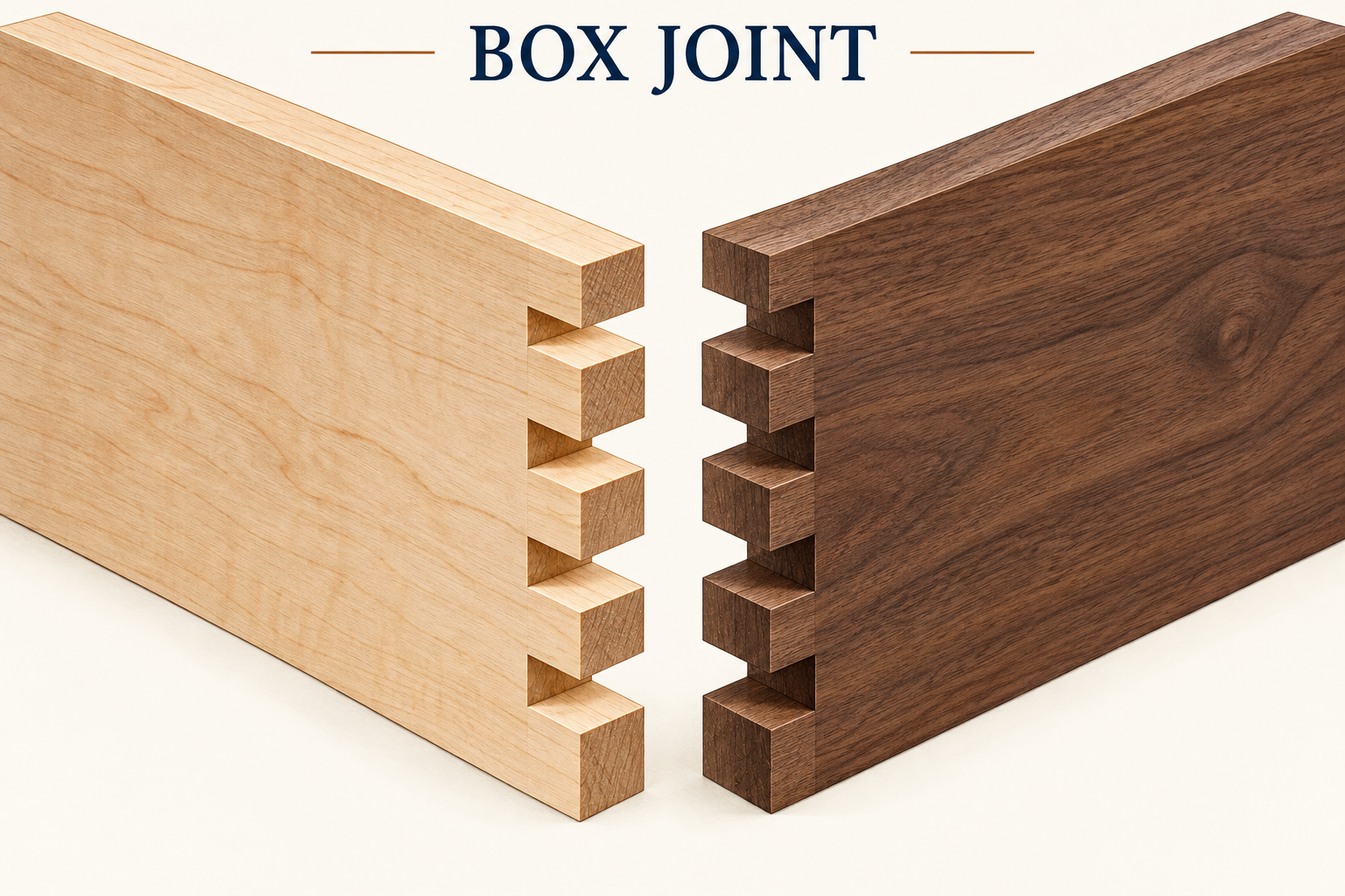
The end pattern must be complementary. Where one board has a finger, the mating region needs a space. Looking only at the repeated cuts on one board misses that relationship. The corner has to be considered as a pair, with the intended inside faces and top edges identified.
Spacing and the starting pattern work together
Rockler’s box-joint jig uses indexing keys matched to the cutter system to establish repeated spacing. This illustrates why the cutter and the indexing arrangement must be considered together. A nominal cutter description alone does not establish the resulting mating fit.
The starting relationship between adjacent boards is a separate layout decision. The cited jig manual distinguishes the first board from its mating board rather than treating both ends as identical patterns. The exact method depends on the jig; a generic illustration should not become an adjustment instruction for every system.
Before reviewing a test pair, identify which faces and edges are meant to correspond. If those references are mixed up, a good-looking sequence of fingers may still be on the wrong end or face. This is a layout question before it is a question about cutter quality.
Describe the mismatch before changing the setup
| Observation | Question it raises | Keep separate |
|---|---|---|
| Fingers do not enter their matching spaces as intended | Is the lateral fit correct for this pair? | Finger projection beyond the adjoining surface |
| Fingers face fingers at the intended corner | Is the mating pattern complementary? | The width of an otherwise suitable finger |
| Ends stand proud or finish recessed | Does projection suit the planned finished joint? | Whether fingers and spaces have the intended lateral fit |
The manual treats finger projection and spacing as separate matters. That distinction is useful when recording a test result: describe what the assembled surfaces show rather than applying one label such as “too tight” to every visible problem.
A projection difference does not automatically prove a lateral-fit problem. Likewise, correcting a starting-pattern error does not prove that the remaining fit is appropriate. Recheck the relevant observation against the exact jig’s instructions instead of assuming one adjustment resolves everything.
Use a test pair that represents the project
The cited instructions call for test pieces with the same thickness as the final workpieces. This matters because a trial made from unrelated stock does not represent every geometric relationship in the intended corner. Keep the trial identified with its stock and jig configuration.
For a hypothetical small presentation box, a useful test record names the two mating pieces, their inside faces and their top edges. It then records the lateral fit, whether the end patterns complement each other, and the observed finger projection. A photograph can supplement those notes without replacing the references.
If the trial has a starting-pattern problem, record that finding precisely. If the pattern is correct but the fit is unsuitable, record the different finding. This gives the next review a defined problem and avoids discarding useful information about the parts of the joint that already match.
The full cutting method remains specific to the jig, cutter and machine. This guide supplies no router speed, cutter-height value or universal direction for moving an indexing key. Use the equipment instructions for that work and evaluate the test pair before committing the project parts.
A clear box-joint review ends with a complementary pair, an intentional fit and a defined finished surface. Keeping those judgments separate makes both layout mistakes and cutting-related fit problems easier to communicate.