


Countersink vs Counterbore: Hole Geometry, Fastener Heads and Drawing Callouts
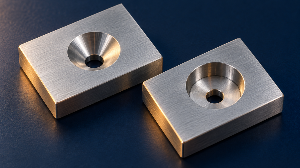
A countersink is a conical recess; a counterbore is a larger cylindrical recess with a flat seat. The countersink vs counterbore choice starts with the fastener’s bearing surface and the required head position. Both features can recess a screw head, but their shapes are not interchangeable.
A drawing that says only “make the screw flush” leaves important information unresolved. It does not identify the head geometry, the recess dimensions or the finished position relative to the part surface. Those details decide whether the intended fastener seats correctly.
Countersink vs counterbore: the difference in section
Look at the material removed around the smaller hole. A countersink opens outward through sloping conical walls. A counterbore has straight cylindrical walls and a flat seating shoulder around the smaller bore. The section view makes this distinction clearer than a photograph taken directly above the part.
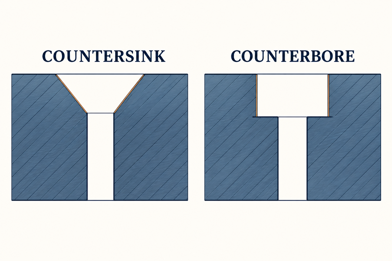
Protolabs’ CNC hole-design guide distinguishes these geometries and their fastener uses. A flat-head screw is a common reason to specify a countersink. A counterbore can accommodate a socket-head or similar fastener with an appropriate flat bearing surface. The selected fastener drawing remains the reference for the actual head.
The feature name describes a shape. It does not, by itself, establish a screw size or a finished assembly condition. A conical mouth can be visible on a part without proving that it was dimensioned to seat the screw in your assembly.
| Question | Countersink | Counterbore |
|---|---|---|
| What is the recess shape? | Conical | Cylindrical, with a flat seat |
| What head form commonly motivates it? | Matching tapered underside | Matching flat bearing underside |
| What still needs definition? | Actual recess geometry and head position | Actual recess geometry and head position |
Match the seat before describing the appearance
“Flat head” describes a fastener style, while “flat seat” describes the bearing surface in the part. Confusing those phrases can reverse the intended feature. A flat-head screw normally presents a tapered underside; a cylindrical screw head may present a flat underside.
The desired appearance comes next. A head might be intended to finish flush, sit below the surrounding surface or remain proud. Its final position depends on the actual fastener and recess dimensions. Neither the word countersink nor counterbore guarantees a flush result without those details.
For an assembly review, place the fastener section beside the part section. Identify the surfaces intended to bear against each other, then identify the surface used to judge head height. This comparison exposes a geometry mismatch before the discussion moves into tooling or supplier quotations.
Give the drawing a complete requirement
An effective handoff describes the head, seat and result. The head identifies the fastener geometry. The seat identifies the recess required in the part. The result identifies the finished head position and the dimensions that control it.
For example, consider a hypothetical cover plate whose screw head must stay below an adjacent sliding component. A note requesting a “recessed screw” does not answer whether a tapered or flat bearing seat is intended. Naming the fastener and showing the required section makes that question explicit.
The drawing must then supply the relevant dimensions and tolerances. The cited hole-design guide identifies omitted countersink angles and poor tool access as design problems. A familiar-looking symbol or a generic photograph cannot replace the missing requirement.
For a countersink, identify the smaller hole, the recess diameter and its included angle, with the required tolerances. For a counterbore, identify the smaller hole, the larger recess diameter and its depth, with the required tolerances. Tie these fields to the intended head position rather than selecting values from a generic illustration.
The distinction matters during a drawing change. A reviewer can check an angle requirement for the conical seat and a depth requirement for the flat-seat recess. Leaving either field implicit makes the supplier infer part geometry from the desired appearance. The fastening application must provide the actual values; this comparison supplies none.
Keep this record with the actual fastener specification and drawing revision. If the fastener changes, review the recess rather than assuming the old hole remains suitable. A shared nominal thread description does not communicate every detail of the head.
Tool names and sheet processes need a separate check
A tool-library label can create another misunderstanding. Harvey Performance’s CAM naming guidance shows that software classifications and manufacturer tool descriptions do not always use identical terms. Its crosswalk includes flat-bottom drills appearing under a counterbore classification.
Therefore, communicate the required part geometry before selecting a library entry. A software name is a starting point for identifying a tool, not a replacement for checking its shape and intended use.
Sheet-metal work also needs process context. The cited fabrication chart distinguishes formed countersinks from machined countersinks. A solid-block section explains the shape, but does not specify which process suits a particular sheet part. Material, thickness and project requirements still need evaluation.
For the related but broader edge concept, see the chamfered-edge guide. A general edge bevel and a dimensioned screw seat answer different design questions. For a fastener recess, finish the review with the actual head geometry, bearing seat and required assembled position together.