


Chamfered Edge Explained: Shape, Dimensions and Common Comparisons
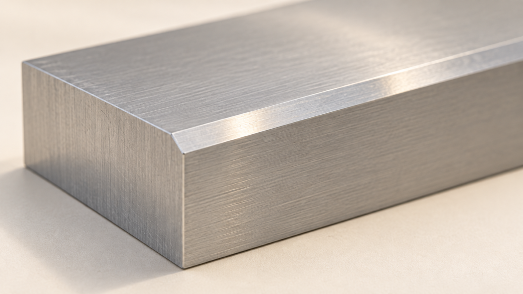
A chamfered edge replaces a sharp corner with a flat, angled transition between two faces. In cross-section, the new edge is a straight sloping line. A rounded edge has a curved transition instead. The difference is easy to recognize, but a finished part also needs the chamfer’s size and location—not just its name.
A small edge break, an assembly lead-in and a larger sloped feature can all involve angled geometry. The drawing should explain which feature is intended, rather than leaving the machinist or inspector to infer it from a photograph.
What a chamfered edge looks like
Imagine the top and side of a rectangular block meeting at a right angle. Removing material across that corner creates a narrow flat face between them. That new face is the chamfer. It can follow an outside edge or appear around an opening, depending on the part design.
James Engineering describes chamfering through the removal of a corner or edge. The important visual clue is the resulting angled transition. A chamfer need not have equal offsets on both adjoining faces, and the word does not prescribe one angle for every part.
Chamfer versus radius or fillet
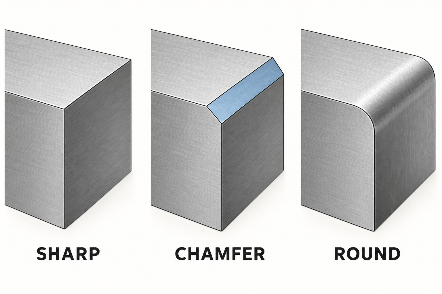
A chamfer is flat; a radius or fillet is curved. Protolabs distinguishes sloped edge breaks from rounded ones in its machining guidance. On an outside corner, the curved feature is often called a round; CAD systems and everyday workshop usage may also describe rounded transitions as fillets.
| Feature | Section shape | Information to resolve |
|---|---|---|
| Sharp corner | Faces meet without an intentional transition | Whether the edge is intended to remain sharp |
| Chamfer | Straight angled transition | Size, angle or two offsets, and affected edge |
| Round or fillet | Curved transition | Radius and affected edge or corner |
| General deburring request | Removal of unwanted burrs | Acceptance condition; it does not by itself define a chamfer |
These descriptions identify geometry and task. They are not a universal ranking of which edge is stronger, cheaper or more appropriate. A deliberate change from a specified chamfer to a radius changes the requested shape, even if both look smoother than the original corner.
Chamfer vs bevel: avoid a false size rule
The words can overlap. Autodesk’s documentation uses “chamfer or bevel” for an angled connection in two dimensions or an angled face between adjacent faces in three dimensions. Some workshop contexts use bevel for a broader sloped surface and chamfer for a local edge treatment, but that habit is not a universal dimensional cutoff.
For a supplier enquiry, a sketch is more reliable than arguing over the label. Identify the affected faces, show the intended transition and state its dimensions. If an existing drawing uses “bevel,” preserve that wording and clarify the geometry rather than silently substituting a different interpretation.
Chamfer dimensions: offsets are not face width
Autodesk documents two ways to define the transition: two distance values, or a distance and an angle. The distances relate to the adjoining objects or faces. The angle also needs a reference. An angle alone leaves the amount of removed material unresolved.
Consider a hypothetical right-angle corner with a 1 mm setback along each face. The equal setbacks produce a 45° diagonal in that cross-section. The sloping line is the triangle’s hypotenuse, so its length is √(1² + 1²) mm, or approximately 1.41 mm. It is not 1 mm.
This is a geometry example, not a recommended chamfer size. Its purpose is to distinguish the setback measured along an original face from the width measured across the new sloping face. Two people can otherwise use the same word “width” while measuring different lengths.
Unequal setbacks produce a different slope. A drawing or model therefore needs enough information to resolve the intended section. Where a compact callout is used, interpret it under the drawing’s stated conventions; do not invent a tolerance or assume that every chamfer means equal setbacks.
Why chamfering and deburring are different requests
Deburring addresses unwanted burrs left by a manufacturing operation. A dimensioned chamfer describes an intentional feature. ALEKVS separates those tasks in its chamfering guidance: burr removal does not automatically establish a controlled angled surface.
A chamfer can also serve as a lead-in for a mating component. That makes its location and geometry functional rather than merely visual. However, the presence of a chamfer does not prove that an assembly will fit; the related dimensions still need to agree.
Compare two hypothetical instructions: “remove burrs from this opening” and “make the indicated entry chamfer to the drawing.” The first identifies an edge-cleanup task. The second requests a particular feature. They may be performed within the same production route, but they are not interchangeable acceptance descriptions.
A useful drawing and inspection handoff
A clear edge specification resolves four questions. Shape distinguishes a flat chamfer from a curved transition. Size defines the relevant offsets or distance-and-angle relationship. Location identifies the exact edge, hole entry or side of the part. Acceptance points to the applicable drawing requirements rather than an assumed visual standard.
For example, a photo of a metal block may clearly show a bright sloping strip. It still cannot establish the strip’s dimensions or which edges on another part require the same treatment. A marked drawing can separate the visible feature from the information that remains to be specified.
The same separation helps during cutting-process planning. A blade from a jigsaw blade category is a cutting accessory; that category description does not establish a finished chamfer. Keep blank or profile cutting separate from the edge-finishing requirement when defining the job.
The practical result is an edge that can be discussed and checked against the same definition. “Chamfered” identifies the flat angled form; the accompanying geometry tells everyone which form to make.